Tesera SA Stand-Alone ALIF Cage System
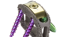
The Tesera® SA Stand-Alone ALIF Cage is a porous titanium Stand-alone Anterior Cage designed to be part of the fusion, rather than merely a vessel for it.
Using additive manufacturing, we have created an ideal trabecular structure for bone in-growth, providing excellent long-term fixation. Four screws and an innovative locking system provide immediate fixation and confidence.

KYOCERA Medical is committed to advancing patient care through better products, based on scientific and clinical data. We commissioned an independent study through IMDS Discovery Research to validate our Tesera Trabecular Technology. Below are images and excerpts from the Twelve Week Draft Report. The final report, with 24 Week data, will be posted upon completion.
A Twelve and Twenty-four Week Study to Quantify the Rate of Bone Growth into a Porous Titanium Device in the Ovine Medial Femoral Condyle.
By: IMDS Discovery Research | 1785 North 730 West | Logan, Utah 84321
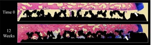
Figure 12: This figure shows an overhead view of the 75 micron stained sections. Black=Titanium, Pink=Bone, Blue=Fibrous Tissue & White=Pore Space. The 12 Week specimen had excellent bone attachment to the porous coating. Note — no bone grafts, synthetics or other extenders were used in this study.Figure 12: This figure shows an overhead view of the 75 micron stained sections. Black=Titanium, Pink=Bone, Blue=Fibrous Tissue & White=Pore Space. The 12 Week specimen had excellent bone attachment to the porous coating. Note — no bone grafts, synthetics or other extenders were used in this study.

Figure 13: This figure shows a comparison of each time point. Black=Titanium, Pink=Bone, Blue=Fibrous Tissue & White=Pore Space. The time 0 specimen shows bone chips (arrows) within the porous structure (PC) and along the drill track in the periprosthetic region (PP). 12 Week specimen shows excellent bone attachment to the porous structure.Figure 13: This figure shows a comparison of each time point. Black=Titanium, Pink=Bone, Blue=Fibrous Tissue & White=Pore Space. The time 0 specimen shows bone chips (arrows) within the porous structure (PC) and along the drill track in the periprosthetic region (PP). 12 Week specimen shows excellent bone attachment to the porous structure.
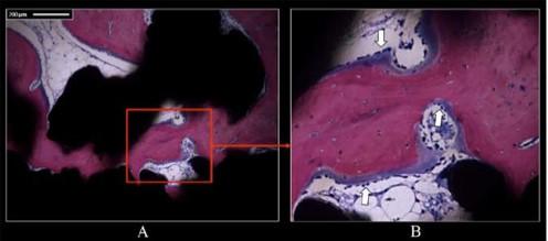
Figure 14: This figure shows bone ingrowth and remodeling within the porous structure on the 12 week specimen. Black=Titanium, Pink=Bone, Blue=Fibrous Tissue & White=Pore Space. (A) 10x image showing bone attachment to the porous structure, (B) Higher power image of (A) (red box) showing osteoblastic activity (arrows) within the porous coating.Figure 14: This figure shows bone ingrowth and remodeling within the porous structure on the 12 week specimen. Black=Titanium, Pink=Bone, Blue=Fibrous Tissue & White=Pore Space. (A) 10x image showing bone attachment to the porous structure, (B) Higher power image of (A) (red box) showing osteoblastic activity (arrows) within the porous coating.
Features and Benefits
The Tesera ALIF Cage features an ideal trabecular structure for bone in-growth, providing excellent long-term fixation.
01 Truly porous
Using additive manufacturing, the entire cage is “grown” layer upon layer, in much the same fashion as traditional rapid prototyping, but instead of plastic, we use titanium alloy powder. The final product is a solid structure in the middle, transitioning to a porous structure at the surfaces.
- True porous surfaces (1.15mm thickness)
- Solid superstructure below the porous layer
- Made from Titanium (Ti6Al4V) powder
- Melted into a solid form by electron beam laser
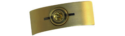
02 Locking Cover Plate
A quarter turn is all that it takes to lock all four screws. And with tactile and visual confirmations, you can be confident the system is locked before you close the wound.
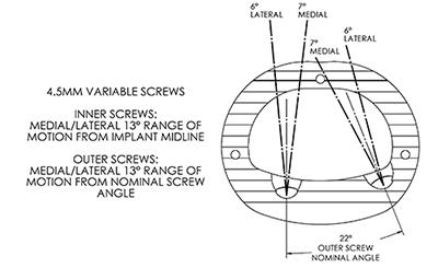
03 Screw Angles
Our screw angles are set to provide maximum stability while minimizing risk to surrounding tissue and vascular structures.
04 Graft Chamber
Our cage is designed for strength without the need for braces or crossbars through the middle of the cage. This allows for an extra large graft chamber to maximize the potential for a solid, rapid fusion.

Sizes and Specs
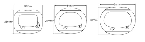
01 Dimensions
| 30mm(W) x 26mm(D) | 34mm(W) x 28mm(D) | 38mm(W) x 30mm(D) | |
|---|---|---|---|
| 7 Degree Lordosis | 11 | 11 | 11 |
| 13 | 13 | 13 | |
| 15 | 15 | 15 | |
| 17 | 17 | 17 | |
| 19 | 19 | 19 | |
| 12 Degree Lordosis | 11 | 11 | 11 |
| 13 | 13 | 13 | |
| 15 | 15 | 15 | |
| 17 | 17 | 17 | |
| 19 | 19 | 19 |
02 Graft Chamber
| Part Number | Width | Depth | Height | Lordosis | Graft Window Volume | |
|---|---|---|---|---|---|---|
| 1128-302-611 | 30mm | 26mm | 11mm | 7° | 2270mm3 | 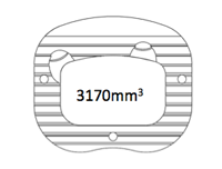 |
| 1128-302-613 | 30mm | 26mm | 13mm | 7° | 2770mm3 | |
| 1128-302-615 | 30mm | 26mm | 15mm | 7° | 3270mm3 | |
| 1128-302-617 | 30mm | 26mm | 17mm | 7° | 3780mm3 | |
| 1128-302-619 | 30mm | 26mm | 19mm | 7° | 4280mm3 | |
| 1129-302-611 | 30mm | 26mm | 11mm | 7° | 2060mm3 | |
| 1129-302-613 | 30mm | 26mm | 13mm | 7° | 2560mm3 | |
| 1129-302-615 | 30mm | 26mm | 15mm | 7° | 3060mm3 | |
| 1129-302-617 | 30mm | 26mm | 17mm | 7° | 3570mm3 | |
| 1129-302-619 | 30mm | 26mm | 19mm | 7° | 4070mm3 | |
| 1128-342-811 | 34mm | 28mm | 11mm | 7° | 2940mm3 | 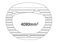 |
| 1128-342-813 | 34mm | 28mm | 13mm | 7° | 3600mm3 | |
| 1128-342-815 | 34mm | 28mm | 15mm | 7° | 4250mm3 | |
| 1128-342-817 | 34mm | 28mm | 17mm | 7° | 4910mm3 | |
| 1128-342-819 | 34mm | 28mm | 19mm | 7° | 5560mm3 | |
| 1129-342-811 | 34mm | 28mm | 11mm | 7° | 2610mm3 | |
| 1129-342-813 | 34mm | 28mm | 13mm | 7° | 3270mm3 | |
| 1129-342-815 | 34mm | 28mm | 15mm | 7° | 3920mm3 | |
| 1129-342-817 | 34mm | 28mm | 17mm | 7° | 4570mm3 | |
| 1129-342-819 | 34mm | 28mm | 19mm | 7° | 5230mm3 | |
| 1128-383-011 | 38mm | 30mm | 11mm | 7° | 3950mm3 | 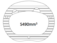 |
| 1128-383-013 | 38mm | 30mm | 13mm | 7° | 4840mm3 | |
| 1128-383-015 | 38mm | 30mm | 15mm | 7° | 5740mm3 | |
| 1128-383-017 | 38mm | 30mm | 17mm | 7° | 6630mm3 | |
| 1128-383-019 | 38mm | 30mm | 19mm | 7° | 7530mm3 | |
| 1129-383-011 | 38mm | 30mm | 11mm | 7° | 3450mm3 | |
| 1129-383-013 | 38mm | 30mm | 13mm | 7° | 4340mm3 | |
| 1129-383-015 | 38mm | 30mm | 15mm | 7° | 5240mm3 | |
| 1129-383-017 | 38mm | 30mm | 17mm | 7° | 6130mm3 | |
| 1129-383-019 | 38mm | 30mm | 19mm | 7° | 7030mm3 |